

Blog - Diff repair and upgrade, Ball Joint upgrades and Prop Shaft upgrades - Part 4
On our last ride of 2023, I stopped mid-way up a long moderate hill climb to wait on my buddies to catch up. I went to start back up the hill but couldn't help notice that I no longer had AWD. The back tires were spinning but the fronts were not and I wasn't going anywhere. Sound familiar to anyone? This was about the 3rd or 4th time this had happened since the AWD problems started on a ride at Holy Cross last summer. In the past, I had always been able to get it to go in AWD by putting it in reverse and flipping the AWD switch on and off a few times. This time, it was a no go. After about 10 minutes of fooling around with it, I had my buddies clear off the trail behind me, I backed way down the hill and took a run at it. Fortunately, I got up the hill ok but then found myself in approximately 10" deep snow. Of course without AWD, the machine wants to push through any turns in the snow. I had the wheels turned hard right and all of the sudden the AWD engaged hard with a jerk. It was right then that I decided it was time to address the problem with the AWD before it really stranded me or I did damage to the diff internals. We had already sold enough RS1 diff cover/magnets, that I was convinced a weak magnet was most likely the problem. To this point in time, I hadn't observed any other symptoms to make me think otherwise. Since I was going to have some down time on my rig, I decided to also address the two main remaining weak points on the machine, the prop shaft and the ball joints. At this point, my machine had just over 1000 miles on the clock, not a real impressive life span for the diff but I have been running 35s since day one.
This was my first time taking the front suspension or drive train apart on the Turbo R so I'll share here some of the things I learned along the way. This is not intended to be a step by step how to article but more of tips, tricks and lessons learned write up.
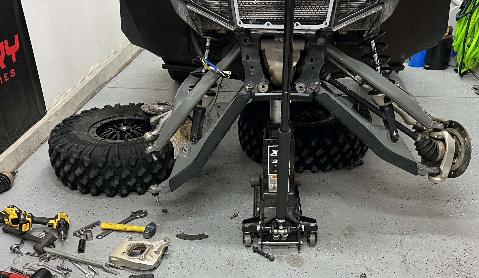
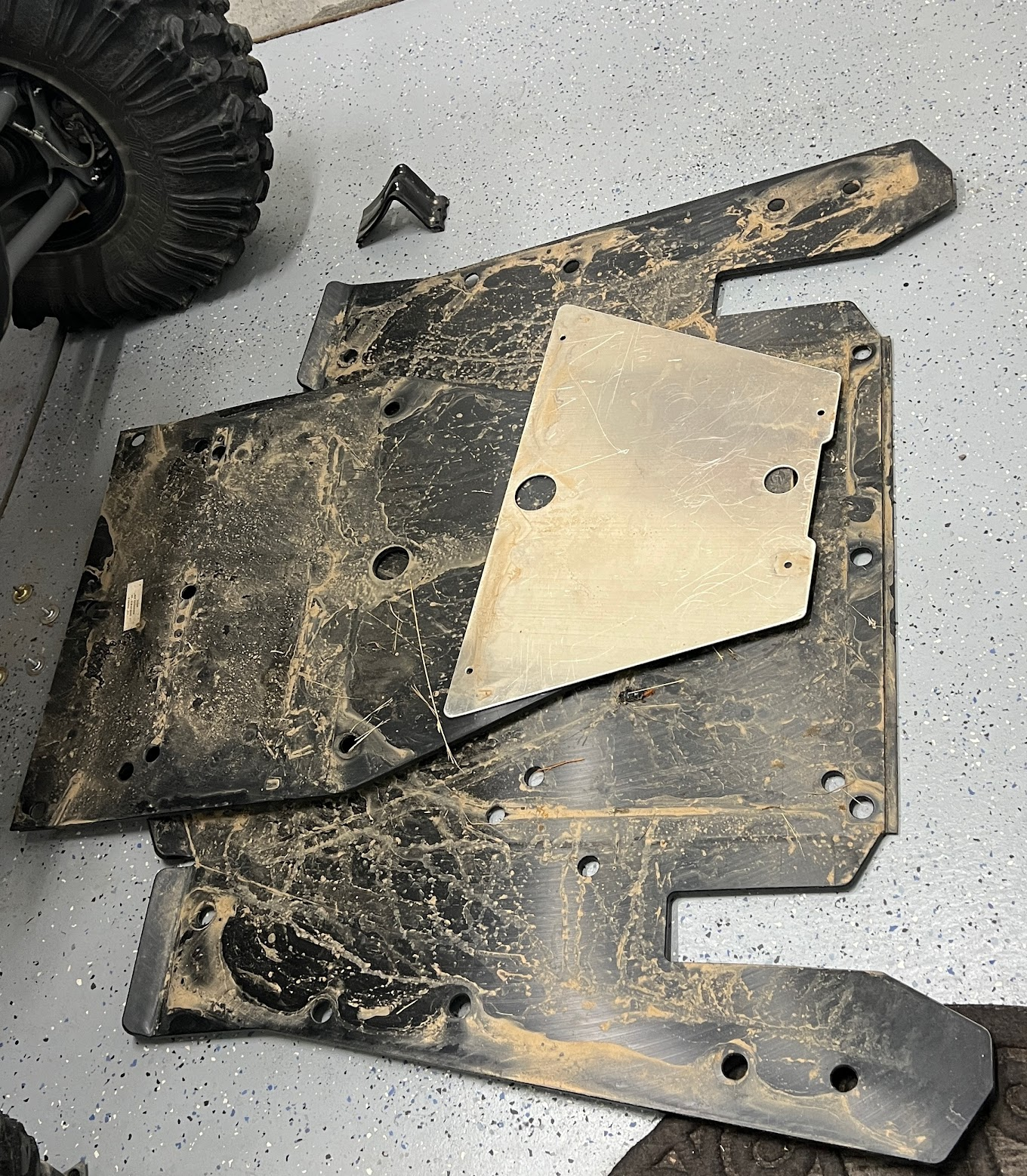
To start, it's a bit of a conundrum on how to jack the machine up and safely support it since the lower a-arms and main skid plates have to come off for this project. This makes it almost impossible to use Jack stands for the front unless you drop the main skid plate first and support the machine with jack stands on the frame rails, then lower the front skid onto a jack stand. I didn't really think about this until I had it jacked up like this (shown below) and part of the suspension torn apart and the main skid plate still intact. Even if you do use jack stands, I ended up needing to roll the machine a few inches to rotate the prop shaft to be able to get a good line on the roll pin on the prop shaft. Today, I loaded the "Jack Rod" from AGM into our website and realized while loading it in just how much safer and more convenient this could have been with just a jack and a Jack Rod. If you are lucky enough to have a lift, I'd drop the skid plates first, then lift the machine from the frame.
One of the first things to do is remove the front bumper or fascia and the winch, if you have one. This is pretty simple to do and probably took less than 5 minutes with the Polaris Full coverage bumper and Polaris winch.
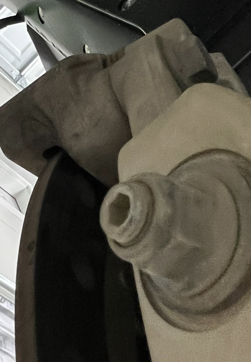
After taking apart the passenger side suspension, I realized I didn't have to take the unitized hub out of the knuckle as you can see I did in the photo. The ball joint on the steering tied rod did not want to come out of the knuckle. I finally got it out with some heat to the knuckle and some banging on it with a 2lb hammer. Turns out I didn't need to do this, I probably should have watched more YT videos or read more write ups in preparation lol!
You will need just about every size socket and or wrench from 15mm all the way up to 21mm plus a 30mm for the axle stub. I found that a 21mm box end wrench is pretty much mandatory to get the upper rear A-arm bolts out.
When you unbolt the lower ball joint from the knuckle, it is good to note that you can put an allen wrench in the bottom of the OEM ball joint to keep it from spinning when tightening or loosening the flange nut. I didn't end up needing it either way with an impact, but it's there.
Another interesting thing to note, the upper bolt for the brake caliper cannot be completely removed from the knuckle without taking off the steering tie rod ball joint from the knuckle. If you do take things this far apart, make sure you put that upper bolt for the caliper back in its hole before you put the tie rod back in the knuckle, otherwise there's no way to get the bolt back in with the tie rod attached to the knuckle!

Although you can unbolt the brake line from the knuckle, there are four more attachment points for the brake line to the upper a-arm. Since the upper a-arm has to come out to get to the diff, you will have to drill out the rivets attaching the brake line to the upper a-arms. Maybe you could tie the a-arms up and out of the way but that seems like it would be more of a pain than drilling out the rivets and replacing them later.

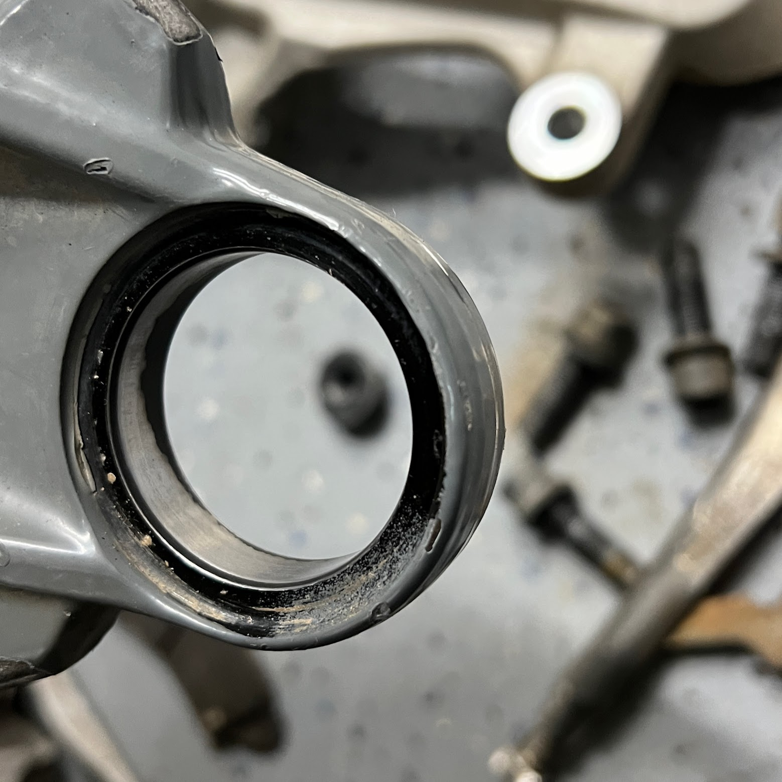
I have a pretty decent ball joint tool but the ball joints were in there TIGHT! The way Polaris made the A-arms, the sleeves you use from an automotive style ball joint tool don't want to seat squarely making it VERY difficult to get the ball joints out and the new ball joints back in the a-arms. I see that High Lifter makes a ball joint tool, I am wondering if it works better on these a-arms? I think I'd rather do 4 roll pins than 4 ball joints again.
I did find that sanding the inside of the hole for the ball joints made them go in a little easier:

Now that the roll pin is out, the axles are out, and the upper a-arms are out, you can access the two long bolts that the diff hangs from in the bulk head. Don't forget to disconnect the electrical plug before you start wrestling the diff out of the bulk head. If you unbolt the diff and begin to slide it out of the front of the bulk head an inch or two, you can get to the little hose clamp on the diff vent tube nipple much easier. When you are putting the diff back in, remember to install the vent tube and clamp back on right before you get the diff all the way back in to place in the bulkhead. Once the diff is in all the way, that clamp is pretty much impossible to get to.

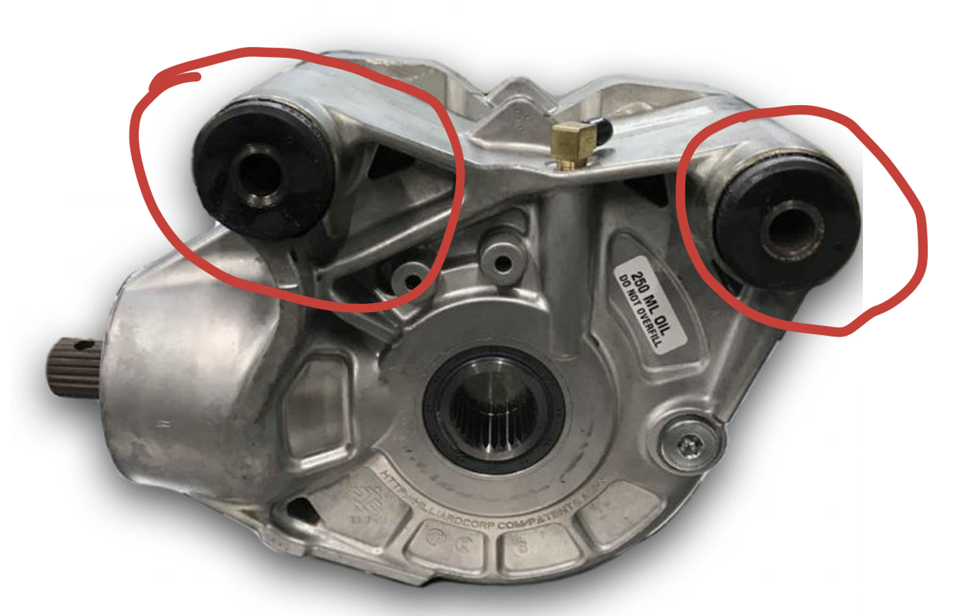
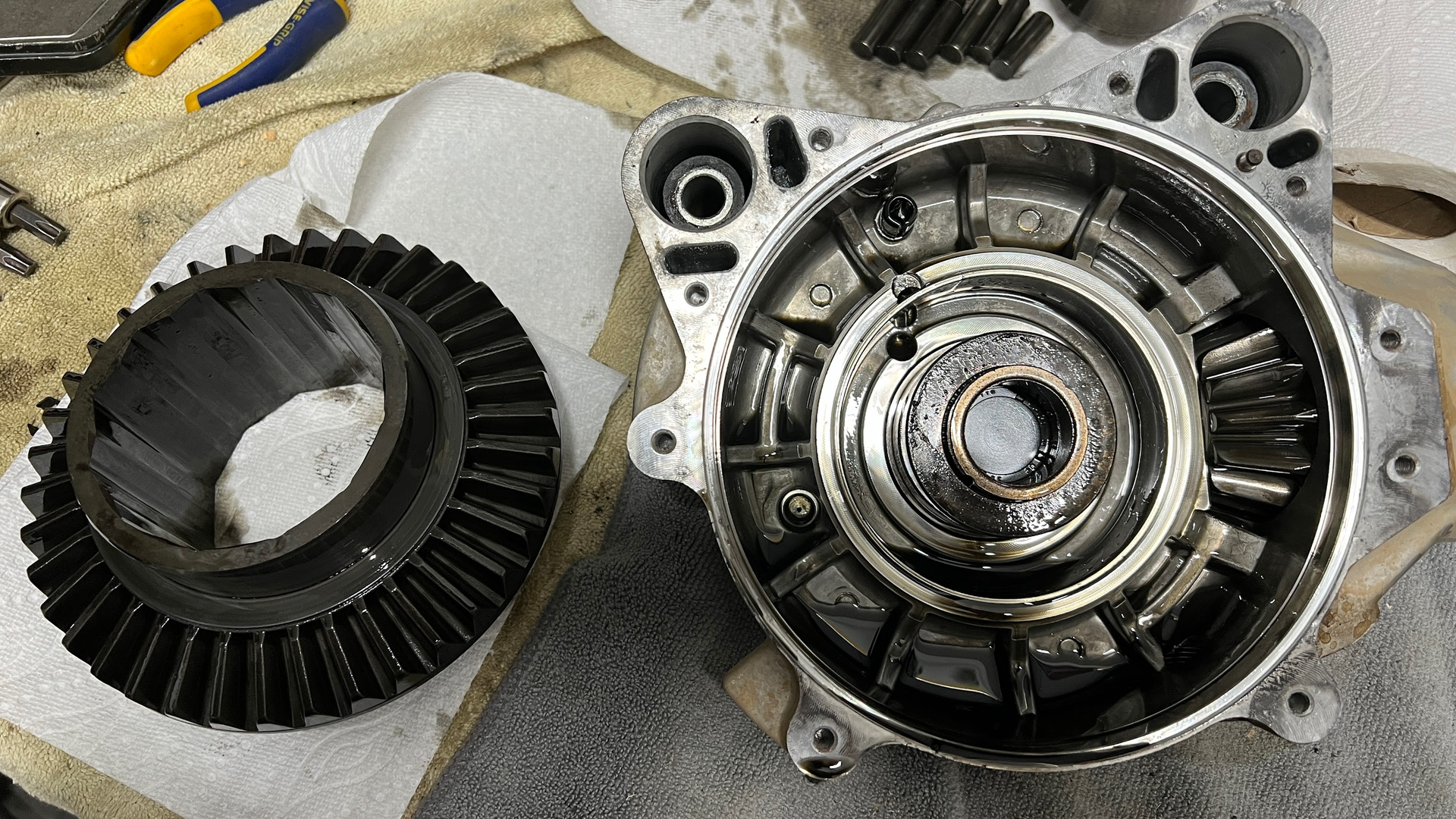
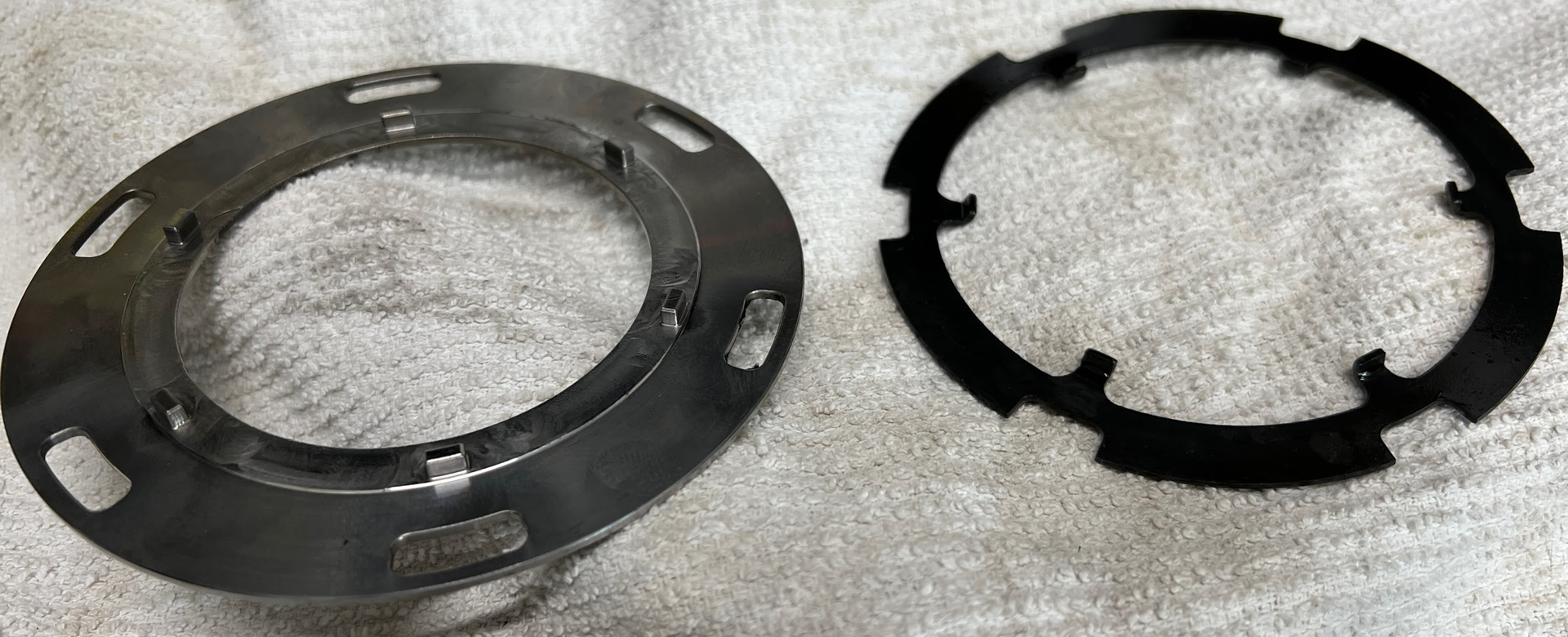
Now that the diff is out, the side cover comes off pretty easily. I think there are around 12x 10mm bolts on the cover then it pries apart pretty easily. I went ahead and took everything apart to inspect it. As I had suspected, the ring and pinion as well as the cage and rollers and output hubs looked fine. The only visible thing was that the dogs on the cage plate looked a little tweaked.

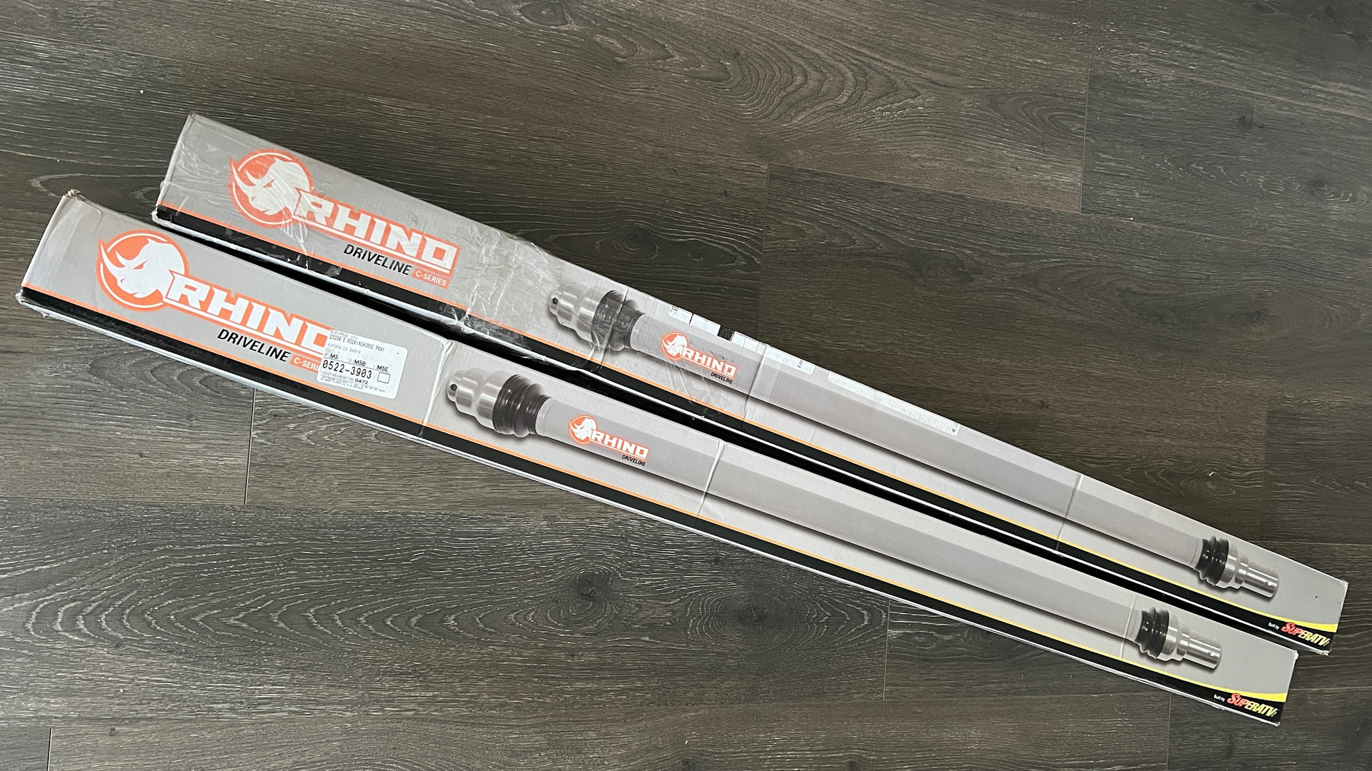
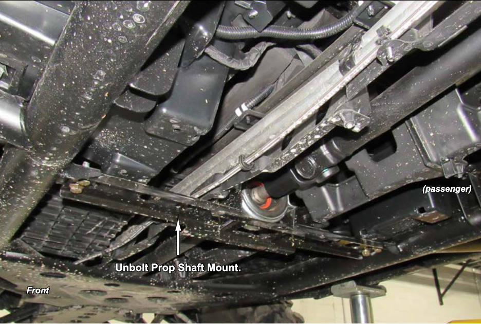
Removing the prop shaft is pretty simple. Super ATV’s instructions for the prop shaft are pretty good so I just followed them for the prop shaft but I took a few notes. Paper instructions did not come in the box btw but you can download them here.
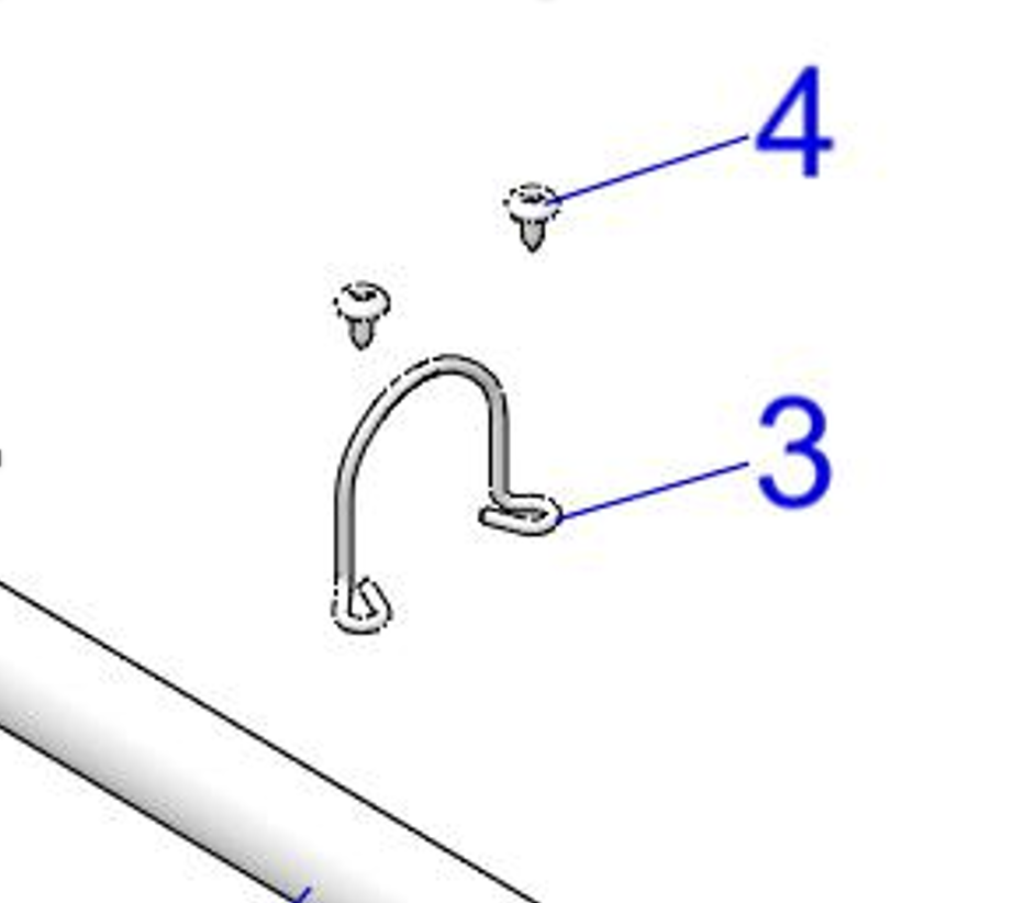
The torx screws on the hoop are kind of hard to get to. Once you break them loose, spray a little WD40 or penetrating oil on them so you can turn them with your fingers easier.
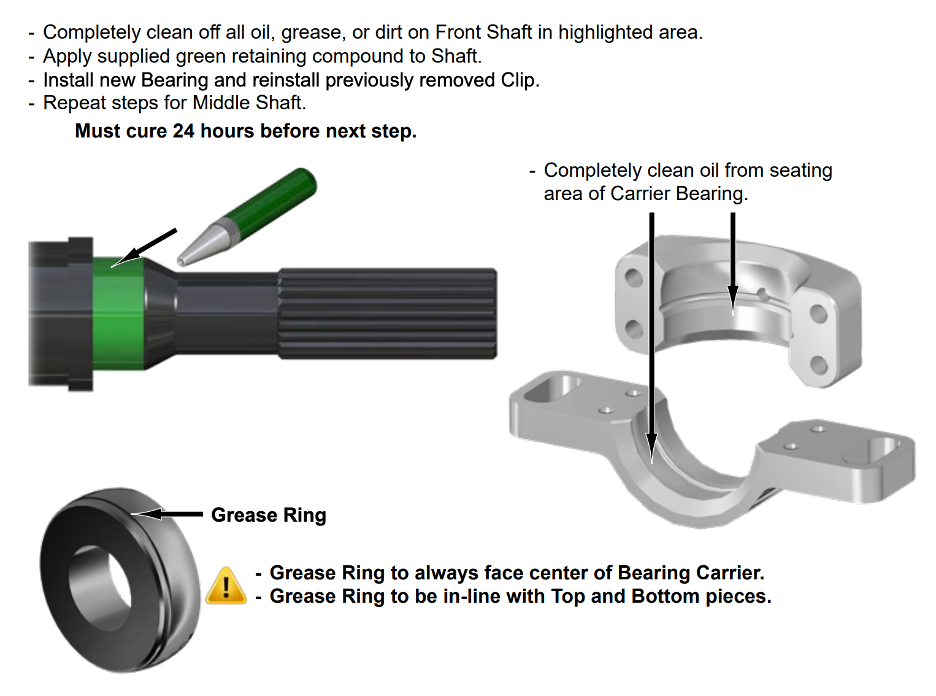
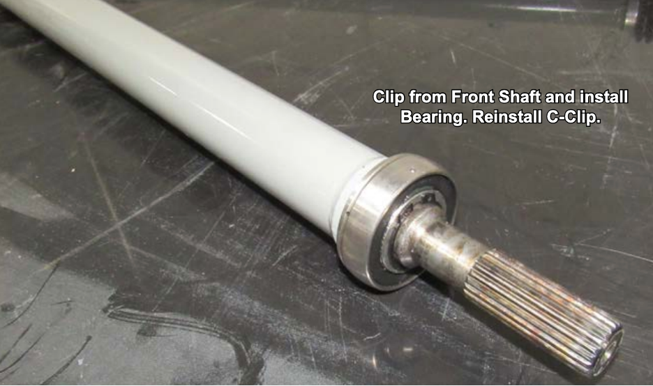
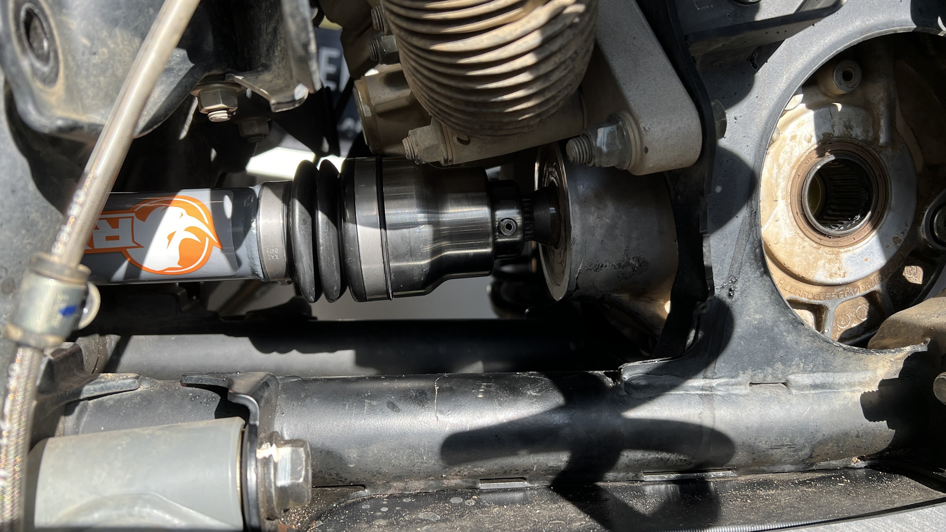
When I installed the prop shaft in my machine, I didn’t have the front diff back in yet. I went ahead and bolted in the carrier bearing and mount for the prop shaft. This was a mistake in the order. If I were to do it over again, I’d put the prop shaft in place and bolt it to the transmission side but do not bolt in the carrier and mount yet. Put the front diff back in, bolt the diff in place and with the carrier section not bolted up yet, you can connect the prop shaft to the diff and put the roll pin in, then bolt the carrier bearing and mount into place. In short, if the carrier is already secured to the frame when you are trying to wrestle the diff back into place, it’s very difficult to also get the prop shaft back on the pinion during the diff install. It’s much easier to get the diff back into position without worrying about the prop shaft, then install the prop shaft later. With the carrier unsecured, that is pretty easy to do.
Don’t miss this step in the prop shaft instructions where you need to install some spacers that come with the prop shaft kit:

At this point in the project, all the hard parts are done, the prop shaft is in, the ball joints are in and the diff is back together an installed. All I had left to do was put all the suspension back together and re-install the winch and front bumper. That is all pretty straight forward so that’s it for lessons learned, tips and tricks on this project. Thanks for reading. If you liked this write up, please consider purchasing your parts and accessories from RockPeak UTV.